Groundworks take-off: strip foundations and drainage
Foundation trench lengths, excavation and concrete volumes, and drainage runs with manholes from a foundation plan. Drawing: Garage/workshop foundation and drainage plan, 1:100. Read with the Groundworks trade profile on 15 November 2026.
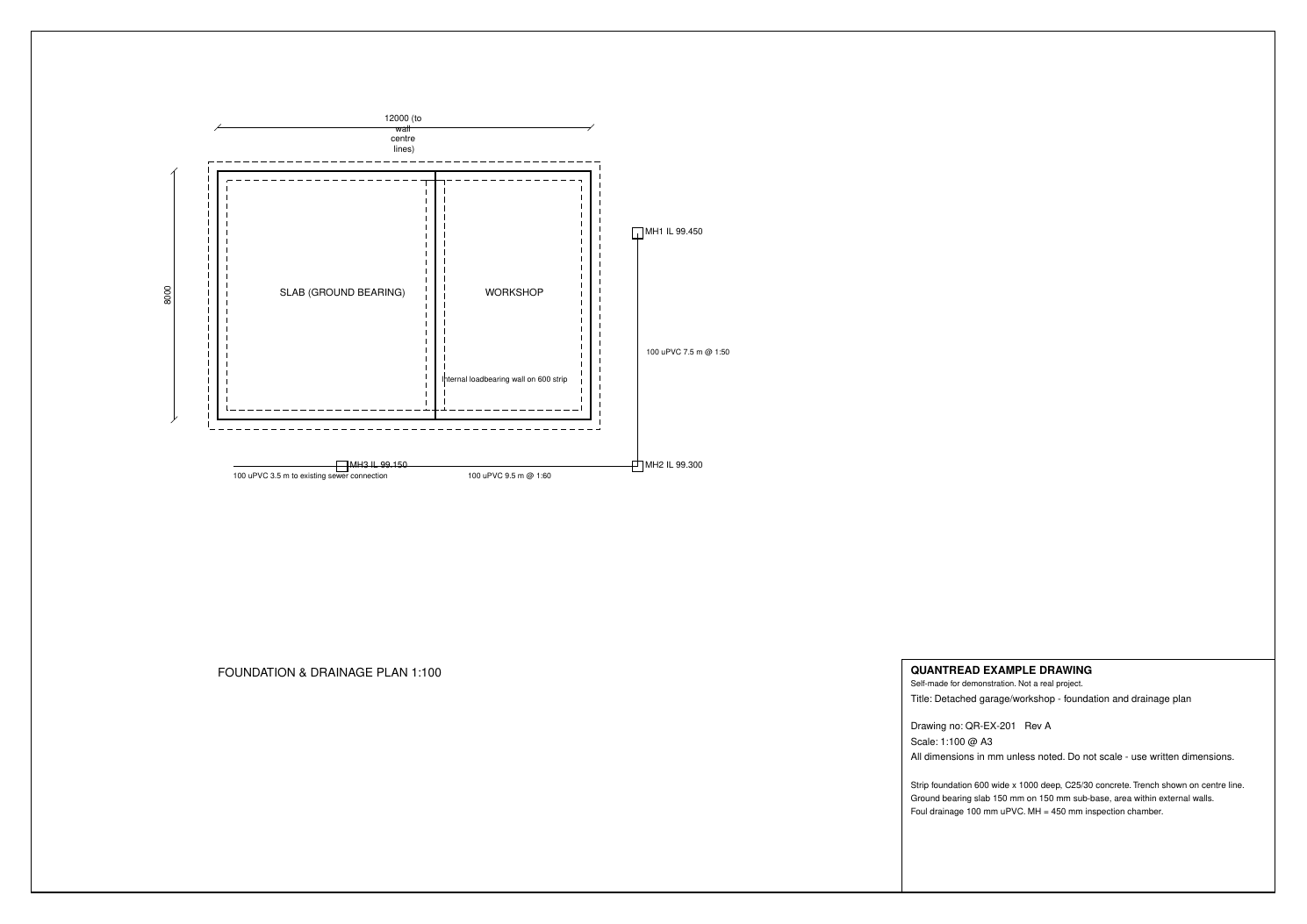
Take-off produced
| Item | Detail | Qty | Unit | Confidence | Note |
|---|---|---|---|---|---|
| External foundation trench plan area | 600 mm wide trench | 24 | m2 | high | Page 1 |
| Internal foundation trench plan area | 600 mm wide; junctions with external trenches excluded | 4.4 | m2 | medium | Page 1 |
| External foundation trench excavation | 600 mm wide x 1000 mm deep | 24 | m3 | high | Page 1 |
| Internal foundation trench excavation | 600 mm wide x 1000 mm deep, assumed same depth as external strip | 4.4 | m3 | medium | Page 1 |
| External strip foundation | 600 mm wide x 1000 mm deep, C25/30 | 40 | m | high | Page 1 |
| Internal loadbearing wall strip | 600 mm strip; length between inside faces of external trenches | 7.4 | m | medium | Page 1 |
| Foul drain 100 mm uPVC | pipe_dia_mm 100; foul_or_surface foul | 20.5 | m | high | Page 1 |
| Inspection chambers | 450 mm inspection chambers; no gullies shown | 3 | nr | high | Page 1 |
| Strip foundation concrete C25/30 | 600 mm x 1000 mm section, assumed full-depth concrete | 28.4 | m3 | medium | Page 1 |
Exports from this run: CSV · PDF report
These figures are the engine’s output, unedited. In QuantRead you review every line, correct anything that is wrong and add your own items before you export or quote.
Our check against the drawing
We drew this example, so we know the figures its written dimensions give. The engine also spotted a slip in our drawing: the MH2 to MH3 run is labelled 1:60 but the inverts give about 1:63. That is our drawing error, flagged in its check-on-site list.
| Item | QuantRead | From the drawing | Comment |
|---|---|---|---|
| External strip foundation (centre line) | 40 m | 40 m | 2 x (12 + 8) m. Matches. |
| Internal strip | 7.4 m | 7.4 m | 8 m less two half trench widths. Matches. |
| Trench excavation | 24 + 4.4 m³ | 28.44 m³ | 0.6 x 1.0 x 47.4 m. Matches (rounded). |
| Foul drain 100 mm | 20.5 m | 20.5 m | 7.5 + 9.5 + 3.5 m. Matches. |
| Inspection chambers | 3 nr | 3 nr | Matches. |
| Slab area | not measured | needs wall thickness | Our drawing gives no wall thickness, so the engine left the slab blank and listed it to check instead of guessing. |
No manual correction was needed on this sample.
How QuantRead measured it
Scale and sheet
Scale: 1:100 @ A3
Checked against: Not scaled — written dimensions used, as the sheet instructs. Annotated 1:50 and 1:60 are pipe gradients, not view scales.
Several scales on this sheet (1:50, 1:100): each view uses its own scale.
How each line was measured
| Pg | Item | Qty | Unit | Basis | Conf. | Method |
|---|---|---|---|---|---|---|
| 1 | External foundation trench plan area External wall centre line | 24 | m2 | dimensioned | high | Centre-line girth 40.0 m x 0.6 m = 24.0 m2 |
| 1 | Internal foundation trench plan area Internal loadbearing wall | 4.4 | m2 | dimensioned | medium | Additional length 7.4 m x 0.6 m = 4.44 m2, reported as 4.4 |
| 1 | External foundation trench excavation External wall centre line | 24 | m3 | dimensioned | high | 40.0 m x 0.6 m x 1.0 m = 24.0 m3 |
| 1 | Internal foundation trench excavation Internal loadbearing wall | 4.4 | m3 | dimensioned | medium | 7.4 m x 0.6 m x 1.0 m = 4.44 m3, reported as 4.4 |
| 1 | External strip foundation Perimeter, trench on centre line | 40 | m | dimensioned | high | Centre-line girth 2 x (12.0 + 8.0) = 40.0 m. 12000 mm is written to wall centre lines; the 8000 mm dimension ends on the same dashed centre line. |
| 1 | Internal loadbearing wall strip Wall between slab bay and workshop | 7.4 | m | dimensioned | medium | Spans the 8.0 m centre-line width. Additional length 8.0 − 0.6 = 7.4 m so the two junctions are not measured twice. |
| 1 | Ground-bearing slab within external walls Both bays, within external walls | not measured | m2 | dimensioned | low | Centre-line sizes are written, but the area within external walls needs the wall thickness, which is not given. Not scaled. |
| 1 | Foul drain 100 mm uPVC MH1–MH2 7.5 m; MH2–MH3 9.5 m; MH3 to existing sewer 3.5 m | 20.5 | m | dimensioned | high | Written lengths 7.5 + 9.5 + 3.5 = 20.5 m. Not remeasured and not adjusted for chamber size. MH1 to MH2 fall of 150 mm in 7.5 m agrees with 1:50. |
| 1 | Inspection chambers MH1 IL 99.450, MH2 IL 99.300, MH3 IL 99.150 | 3 | nr | counted | high | Three chamber symbols counted once each across overlapping tiles. Existing sewer connection is not a new chamber. |
| 1 | Strip foundation concrete C25/30 External and internal strips | 28.4 | m3 | dimensioned | medium | Net trench length 47.4 m x 0.6 m x 1.0 m = 28.44 m3, reported as 28.4. Junctions not double-counted. |
Check on site
- p1: Confirm the 8000 mm dimension is to wall centre lines; the caption is written only on the 12000 mm dimension.
- p1: External wall thickness not shown — slab area, slab concrete and sub-base quantity cannot be calculated.
- p1: Ground and cover levels not shown — reduced-level excavation, drainage trench depth and manhole depths cannot be calculated.
- p1: Confirm the internal strip is 1000 mm deep and that concrete fills the full section.
- p1: MH2 to MH3 invert drop is 150 mm in 9.5 m (1:63); the annotation says 1:60.
- p1: Invert and gradient of the 3.5 m run to the existing sewer are not shown.
Assumptions
- 8000 mm taken as centre-to-centre, on the same dashed trench centre line as the 12000 mm dimension.
- Internal strip extra length measured between the inside faces of the external trenches (8.0 m less 0.6 m) so junctions are not measured twice.
- Internal strip assumed 1000 mm deep, matching the general strip note; depth is not separately written.
- C25/30 assumed to fill the full 600 mm x 1000 mm trench section.
- Slab note applied to the whole area within the external walls, both bays, not only the bay labelled SLAB.
- All 100 mm uPVC runs taken as foul. 1:50 and 1:60 are gradients, not drawing scales.
Scope notes
- Strip foundation trenches on wall centre line, with one internal 600 mm strip.
- Ground-bearing slab on sub-base within external walls; wall thickness not given, so slab area not taken.
- 100 mm uPVC foul drainage and three 450 mm inspection chambers, outfall to an existing sewer.
AI estimate of quantities only. Not a price, a survey or a bill of quantities. Check every quantity against the drawings and on site before you quote or order.
Try your own drawing free
Upload one PDF drawing (up to 3 pages), pick your trade and get an editable take-off like this one.